Jul 012017
 
Suomenkielinen versio täällä.

Why?

One day I just needed an access control system and reservation calendar to a common use sauna, and it had an electric lock (24VAC) already in place.

Hardware (links to Finnish shops):

Stage 1 (memory card):

Raspberry Pi got the newest Raspbian Jessie, which was at the moment in version 2017-06-21. Kernel for the distribution is 4.9.28-v7+.
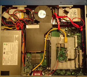
Stage 2 (assembly):

  • detach controller from the TFT (TFT-enclosure required this)
  • assemble the TFT enclosure
  • attach the controller to the TFT, make sure both cables are in place
  • drill holes to the bottom of RasPi enclosure (6mm drill), to use TFT -attachment points
  • insert memory card to RasPi
  • attach RasPi with it’s enclosure to TFT
  • attach the cable from TFT to RasPi, along with 5V(pin4) and Gnd(pin6) with jumper wires
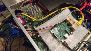
  • attach NFC-reader with jumper wires to RasPi, you’ll use pins 1,3,5,11,12,15,16,19,21-26 (f.ex 3.3V, Gnd, i2c & SPI)
    (Explore NFC Board Schematic)
  • attach relay card module to RasPi, relay needs ~80mAh of current so take note of this when deciding the PSU
    pins 2 (5V -> VCC), 7 (GPIO -> In1) and 9 (Gnd -> Gnd) are needed
  • attach the relay between the another power cable going to the electric lock

Stage 3 (software):

Reader uses SPI, so enable SPI at raspi-config. TFT will rotate by adding display_rotate=1 (90 degrees) or display_rotate=3 (270 degrees) to /boot/config.txt – and console font can be made bigger with dpkg-reconfigure console-setup.

For actual use you need a small stack of software. Relay module must be controller (to open/close door) and NFC-card must be read and validated against some user database. And unless you want to keep the user database up-to-date by hand, there should be something for that also…

My solution was a simple python-service, which reads the NFC-card, validates is against data in MariaDB and after that tells the result on screen & activates the relay if necessary. Almost up to date code can be found at https://macronet.fi/dev/nfc/ (maybe later at github also) – it might work, or not.

Library used for reading the NFC-card is nxppy -that and all other requirements are easy to install:

# sudo apt install python-dev python-pip python-mysqldb cmake mariadb-server-10.0
# pip install nxppy

Stage 4 (installation):

Install the system to the place you want, so that you can show a card to the reader. This might need some cables if you want to take the reader further away – please make note that the reader requires 14 wires (haven’t actually tested if it works without i2c, because it uses SPI) so it’s like 2 cat5e cables.

Stage 5 (why internet connection? and then what?)

Make RasPi to call home/VPN, so that you are able to fix problems remotely.

Or “forget” a wireless keyboard receiver to USB-port and use your new NFC-enabled access control system as an IRC-client.

Jul 012017
 
English version here.

Miksi?

Tulipa eräänä päivänä tarvetta toteuttaa kulunvalvonta ja varauskalenteri erääseen yhteiskäytössä olevaan saunatilaan, missä oli ovenkarmissa jo sähkövastinrauta (24VAC) valmiina.

Käytetty rauta:

Vaihe 1 (muistikortti):

Raspberry Pi  sai sisäänsä uusimman Raspbian Jessien, joka tekohetkellä oli versiota 2017-06-21. Jakelun kernelinä toimii 4.9.28-v7+.

Vaihe 2 (kokoonpano):

  • irrota TFT:stä ohjainkortti (valitsemani kotelo vaati tämän)
  • kokoa TFT:n kotelo näytön ympärille
  • kiinnitä TFT:n ohjainkortti takaisin paikoilleen, varmista että molemmat lattakaapelit ovat hyvin kiinni
  • poraa raspin kotelon pohjaosaan oikeisiin kohtiin reiät (6mm terällä) TFT:n kiinnikkeitä varten
  • laita muistikortti raspiin
  • kiinnitä raspi koteloineen TFT:n kiinnikkeisiin
  • kiinnitä näytön lattakaapeli sekä virtajohdot 5V(pin4) ja Gnd(pin6) hyppylangoilla raspiin
  • kiinnitä NFC-lukija hyppylangoilla raspiin, tarvitset pinnejä 1,3,5,11,12,15,16,19,21-26 (mm. 3.3V, Gnd, i2c & SPI)
    (Explore NFC Board Schematic)
  • kiinnitä relekortti raspiin, rele tarvitsee toimiakseen ~80mAh eli huomioi tämä virtalähteen mitoituksessa
    tarvitset pinnit 2 (5V -> VCC), 7 (GPIO -> In1) ja 9 (Gnd -> Gnd)
  • kierrätä sähkölukon toinen virtajohto releen kautta

Vaihe 3 (softa):

Lukija käyttää SPI:tä, eli enabloi SPI raspi-config :sta. TFT käännetään pystyyn lisäämällä /boot/config.txt :n display_rotate=1 (90 astetta) tai display_rotate=3 (270 astetta) ja konsolin fonttia saa kasvatettua dpkg-reconfigure console-setup :lla.

Varsinaista käyttöä varten tarvitaan pieni nippu sovelluksia. Pitää esimerkiksi hallita relekorttia (avata/sulkea ovi) sekä lukea nfc-kortteja ja validoida luettu kortti jotain käyttäjäkantaa vasten. Ja ellei halua täyttää käyttäjäkantaa käsin niin niiden ylläpitoa vartenkin on hyvä olla omat sovelluksensa…

Oma ratkaisu oli toistaiseksi yksinkertainen python-service joka lukee nfc-kortin, validoi sen MariaDB:tä vasten jonka jälkeen kerrotaan ruudulla tulos & aktivoidaan rele tarvittaessa. Lähes ajantasalla olevaa koodia löytyy osoitteesta https://macronet.fi/dev/nfc/ (ehkä joskus myös githubissa) – se voi toimia tai olla toimimatta.

NFC-kortin luentaan käytetty nxppy -kirjasto ja muut tarvittavat riippuvuudet on helppo asentaa:

# sudo apt install python-dev python-pip python-mysqldb cmake mariadb-server-10.0
# pip install nxppy

Vaihe 4 (paikalleenasennus):

Asenna järjestelmä haluamaasi paikkaan paikoilleen niin että nfc-lukijalle voi näyttää korttia. Tämä voi vaatia hieman kaapelointia jos haluat viedä lukijan kauemmaksi raspista – huomioithan että lukija kaipaa 14 kaapelia (ei tosin ole tullut testattua _vaatiiko_ se niitä oikeasti, vai voiko esim. i2c:t jättää kytkemättä koska käyttää SPI:tä) eli 2kpl cat-kaapeleita.

Vaihe 5 (miksi internet? mitä sitten?)

Laita raspi soittamaan kotiin/VPN:ään, että pystyt korjaamaan mahdolliset vikatilanteet etänä.

Tai “unohda” usb-porttiin langattoman näppiksen vastaanotin ja käytä uutta nfc-kulunhallintajärjestelmääsi vaikka irkkaamiseen lokaalisti.

Feb 202016
 

I had a classic problem, old server without a remote KVM capabilities – if it goes down, no other chances to debug it than going next to it, plug in a monitor and a keyboard.

Then, one day, an epiphany. There is a “Console redirection” in BIOS, and after a quick enable & check – it really worked. BIOS was accessible over serial connection.

Next step, /etc/default/grub (under Debian) open and GRUB_CMDLINE_LINUX="" -> GRUB_CMDLINE_LINUX="console=ttyS0 console=tty0" will enable Linux console through serial. Switching from #GRUB_TERMINAL=console -> GRUB_TERMINAL="console serial" enables Grub to work with serial.

A quick update-grub made the changes active, and during reboot it was confirmed that the whole boot from bios screen to linux login console was accessible through serial connection.


So what about Raspberry Pi?

setupBy default Pi has a serial console active, which can be accessed through GPIO pins 8 & 10 (Pi B+). This needs to be disabled to make console port usable for userspace, by removing console=ttyAMA0 from /boot/cmdline.txt (or by disabling a correct service). After spending less than 1€ on Ebay (to get “MAX3232 RS232 Serial Port To TTL Converter Module DB9 Connector With Cable”) I had the required hardware to connect them together.

– Fits in 1U?  *** Yes

– Pretty setup?  *** No

– Works?  *** Yes


serialPi was powered via an USB port on the server backplane, a CAT5e -cable was needed for a network connection and the RS232 -converter was plugged into COM1.

Setup through the COM2 header found in the corner of the motherboard would have been nicer, but it just refused to work.

There’s also cables from the Pi into the reset button -pins on the motherboard, because I needed a way to make a hard reset. Power On/Off could also be managed through power button-pins, but for me it’s quite useless because the Pi is powered by the server through USB (and the server is always on).


Now I can access the Pi through SSH-session and use it to access console on the main server, if I ever need to do so.


GPIO connections (Pi B+ -> other end):
Pin 2 -> RS232 converter: VCC
Pin 6 -> RS232 converter: GND
Pin 8 -> RS232 converter: TXD
Pin 10 -> RS232 converter: RXD
Pin 14 -> Motherboard: Reset GND
Pin 16 -> Motherboard: Reset +

Reset-software (python-rpi.gpio required, don’t blame me if it destroys everything):

#!/bin/python
import RPi.GPIO as GPIO
GPIO.setmode(GPIO.BOARD)
GPIO.setup(16, GPIO.OUT)
# We're currently sinking the current through Pi.
# This causes a "push event" on a reset button.
GPIO.setup(16, GPIO.IN)